
Translume
Translume offers a large selection of flow cells for all your lab and instrument needs.
Many of these standard items are available immediately from our stock or on short order.
Translume offers a large selection of standard-design microfluidic chips for all your lab and instrument needs. Many of these items are available immediately from our stock or on short order.
Mixing liquids is easy: Pour milk into your coffee cup, and the mixing is immediate. Except this does not work so well at the microfluidic level. In fact, this does not work at all!
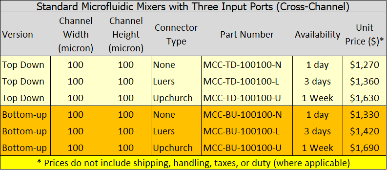
Microfluidic Mixer with Three Input Ports (Cross-channel)
Microfluidic Mixers with THREE Input Ports (CROSS-Channel)
![]() The main channel of this three-input ports fused silica glass microfluidic chip is patterned with asymmetrical sets of chevrons designed to facilitate streams mixing.
The main channel of this three-input ports fused silica glass microfluidic chip is patterned with asymmetrical sets of chevrons designed to facilitate streams mixing.
[Note: Mixing is a function of numerous application specific parameters such as operational pressure, viscosity, etc. – we make no representation that the mixing chips listed below are suitable for your specific application.]
As with all of our standard fused silica glass chips, this model has microfluidic channels with an optically clear (transparent) ceiling and a translucent floor.
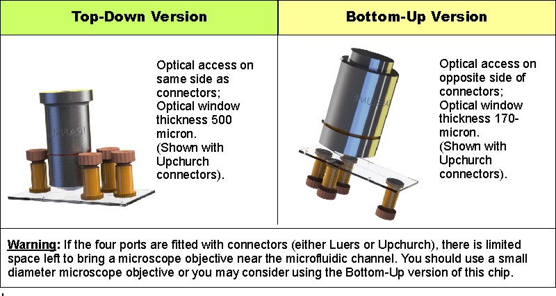
Available in top-down or bottom-up version.
These microfluidic chips are available with or without connectors:
- Without connectors -- part number ends with –N
- With Luer connectors -- part number ends with –L
- With UpChurch Nanoport connectors -- part number ends with -U
** Please note that the bonding agent may extend beyond the connector footprint
Not sure what connectors you need? The following article “What type of connectors should I order?” may help you.
SPECIFICATIONS:
Material and Fabrication
- Made from high-quality Fused Silica Glass
- Layers are thermally fused together
Glass Chip:
- 2" long x 1" wide
- Thickness is either 1.5mm or 1.17mm, depending on Version (Top Down or Bottom Up)
- Graduated reticle (1mm spacing) running perpendicular to channel
- Configuration: Select from table below (Top-Down [Ports on top], or Bottom-Up[Ports on bottom])
Microfluidic Features:
- Microfluidic channel with nearly vertical walls and flat bottom
- Chevron covers ~ 1/2 main channel length (below the junction point)
- Channel Ceiling: Flat, Transparent (Optical quality)
- Channel Floor: Flat, Translucent
- Channel Width: 100 micron
- Channel Height: 100 micron (not including chevrons)
- Fluid Connectors: Select from table below (None, Luer, Upchurch)
Select the chip(s) you want to purchase from the table below and forward your selection to our Sales department
Our glass microfabrication approach is unique, and offers designers and engineers an exceptionally broad range of design options.
Our Custom Fabrication section provides tips and guidelines to facilitate your job as an instrument or microfluidic chip developer.
Most microfluidic chips are made out of several layers, which are somehow bonded together. Typically, one uses two or three layers.
At Translume we have fabricated chips with up nine layers. We fused these layers together using a thermal bonding process
Using Layers to Simplify your Design
For devices that include many functionalities, using multiple layers often simplify the design and the prototyping, possibly lowering the overall fabrication costs.
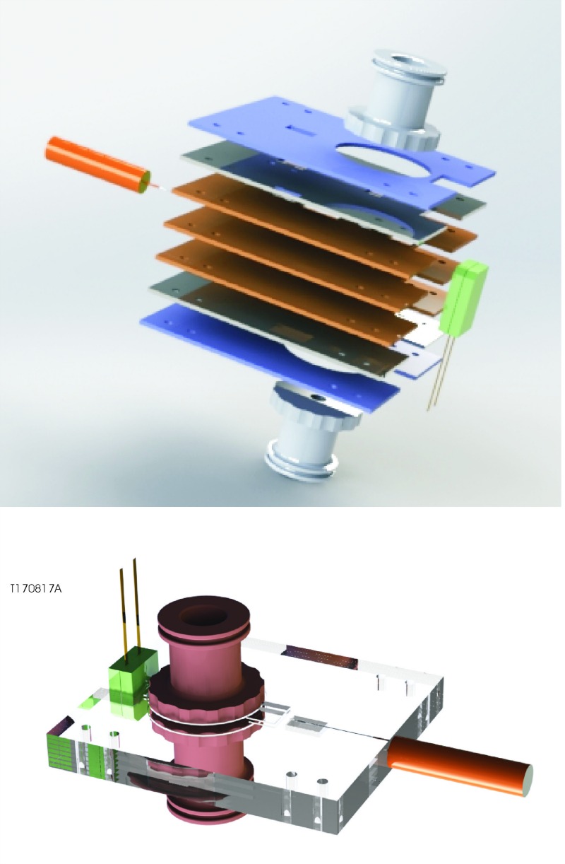
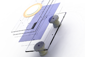
For example the device shown is made with 7 layers:
- The three central layers (colored in brown in the exploded view schematic drawing) contain various integrated optical elements, including an optical fiber port.
- The two outside layers (colored in blue) are designed to facilitate the centering of the two Luer connectors and a photodetector (in green on the right).
- The other two layers (colored in grey) provide some microfluidic functionalities.
During the thermal bonding, air pockets can be permanently trapped between the various layers. To minimize this effect, each glass layer includes some air vents (not shown in these models). This practice reduces the size of the trapped air bubbles, but does not completely eliminate them.
After the thermal bonding, the seven layers form a strong monolith. The Luers, fiber, and photodetectors are added after completion of the thermal bonding.
Most microfluidic chips have a rectangular body, but this doesn’t have to be the case. While a chip with rectangular shape might be relatively easy to fabricate, and at first may appear to be the cheaper fabrication option, there are other considerations that could make an alternate geometry a more cost-effective long-term solution, even if the chip itself is initially slightly pricier.
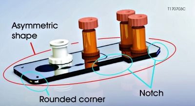
Here are some application-related design elements you may want to consider:
- Ease of Use: Making the body clearly asymmetric will help the users recognize immediately if the part is positioned correctly or if it needs to be flipped or rotated. This is especially useful with transparent parts such as microfluidic chips.
- Extended Lifetime: Rounding the corners of the substrate should reduce the probability that the part will be accidentally chipped during routine handling. Even radii as small as 1-mm may extend the operational life of your device.
- Ease of Handling: Notching the substrate, or adding through-holes for alignment pins, can be used to simplify the positioning of the chip in a fixture or an instrument. (Our manufacturing precision is equal or better than what a typical CNC metal workstation will produce!)
Outside Shape – Some Manufacturing Limitations (not necessarily casted in concrete)
Minimum size: big enough to handle (~ 1 cm2), big enough to allow for connectors (should you want some)
Maximum size: Up to 4” x 4” (Number of layers may impact maximum size)
Standard substrate thickness: 0.25, 0.5, 1 mm, or 2 mm. Thinner substrates available upon request
Tolerances: Outside shape (width, length) ± 50 micron. Higher accuracy available if requested (function of design)
 This section of our website provides tips and guidelines to facilitate your job as an instrument or microfluidic chip developer. Our glass microfabrication approach is unique and offers, scientists and engineers like you, an exceptionally broad range of design options. Below, you will find a collection of technical microfabrication articles and design tips. They are written with microfluidic applications in mind, but many of the fabrication aspects presented here can be applied to other fields as well. Whether you are in microfluidics or not, we hope this section will help you with your design and development program
 Feel free to reach out to us at any time to discuss your precision glass microfabrication questions. We are here to help you and we realize that having real engineers ready to answer design questions is valuable. That's why we staff a team of experienced application engineers who can speak peer-to-peer with you when issues do arise.
Send your questions to This email address is being protected from spambots. You need JavaScript enabled to view it. or call us at (734) 528-6371.
luer adapter kits
How often have you wasted time looking for the right component to interface a small piece of tubing to a microfluidic chip equipped with Luer connectors? “Too often” is the answer in our case.
That does not have to be the case – we offer kits containing Luer adapters to interface your chips with the most common types of tubing. And, at less than $1/piece, these kits will save you money as well as time.
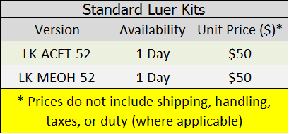
Available in two versions: Acetone-compatible, and Methanol-compatible.
If you will be using Acetone, select kit # LK-ACET-52. This kit can also be used with water and isopropanol. Warning: The components found in this kit should not be used with Methanol (MeOH). They will swell after prolonged contact with MeOH.
If you will be using Methanol, select kit # LK-MEOH-52. This kit can also be used with water and isopropanol. Warning: The components found in this kit should not be used with Acetone. They will degrade immediately (with severe impact) if placed in contact with Acetone.
If you are planning on using both Acetone and Methanol we do not recommend that you use Luers; consider using Upchurch PEEK connectors instead.
SPECIFICATIONS:
Description
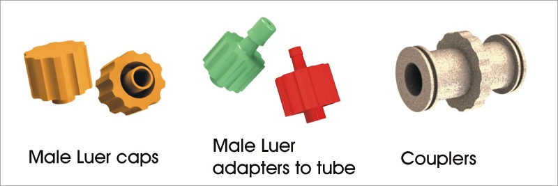
Each kit contains 52 elements:
- 12 Male Luer Caps
- 12 Male Luer Adapters to tube with ID 1/16" (1.6 mm)
- 12 Male Luer Adapters to tube with ID 3/32" (2.4 mm)
- 12 Male Luer Adapters to tube with ID 1/8" (3.2 mm)
- 4 Couplers (female Luer to female Luer)
Material
- LK-ACET-52: Nylon
- LK-MEOH-52: Polycarbonate
Select the kit(s) you would like to purchase from the table below. Contact us either by email or call our Sales office directly at (734) 528 6371 to place your order.
Microfluidic Connector Kits
How often have you wasted time looking for the right component to interface a small piece of tubing to a microfluidic chip equipped with Luer connectors? “Too often” is the answer in our case.
That does not have to be the case – we offer kits containing Luer adapters to interface your chips with the most common types of tubing. And, at less than $1/piece, these kits will save you money as well as time.
Learn more by following this link.