The trap described here was fabricated at Translume under the direction of Dr. Mark Dugan. The trap was designed by the Campbell group [UCLA] and their collaborators at Georgetown University.
Reference: Yoshimura, B., Stork, M., Dadic, D. et al. “ Creation of two-dimensional Coulomb crystals of ions in oblate Paul traps for quantum simulations”, EPJ Quantum Technol. 2, 2 (2015). https://doi.org/10.1140/epjqt14
Application
The Campbell group is using ultra-cold atoms and molecules to learn about the physical processes that permeate the world. Specifically, they are focusing on the physics of quantum mechanical systems that involve many-body interactions, a field where our ability to theoretically describe and numerically simulate the microscopic features is severely limited. Their approach (shared by others, and known in the field as "quantum simulation") is to use well-controlled samples of atoms and molecules in order to build tiny, physical emulators of the physics that they are investigating. By utilizing these atoms as microscopic computers, the Campbell group hopes to be able to pick up where supercomputer simulations become intractable, and to use their quantum simulators to help design and understand new materials, perform demanding computations, and learn about the physical universe.
")
4 rings of ions trapped in an oblate Paul trap (Source: Campbell group - UCLA)
Design Overview
The design (see reference) is optimized to generate an oblate ellipsoidal like effective potential favoring the trapping of ions in a two-dimensional crystal with triangular lattice symmetry. Such a potential can be generated in a Paul trap of azimuthal symmetry with dominant axial confinement. According to the designer, the micromotion in this case is purely radial due to symmetry, and lasers that propagate perpendicular to the crystal plane will therefore not be sensitive to Doppler shifts from micromotion.
Design Implementation
The trap proper is composed of the 5mm outer diameter disc which tapers down to a through hole of 0.5mm diameter and 0.14mm long side wall. These surfaces support the electrodes with the DC control endcaps residing on the upper and lower disc faces and the RF electrode occupying the surface regions constituting the wall and rim of the center hole. The outer frame is such that the DC control electrodes are interfaced through a card connector type clip on the wider end, while the RF is source through the key like structure on the opposite end. This latter RF lead is routed through to the center ring via a subsurface pathway (RF tunnel lead) or as a narrow path on one of the disc faces (surface RF lead). The overall frame size is designed to fit into the UCLA test jig.
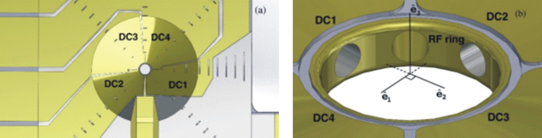
The oblate Paul trap has a combination of DC and RF electrodes used to trap ions.
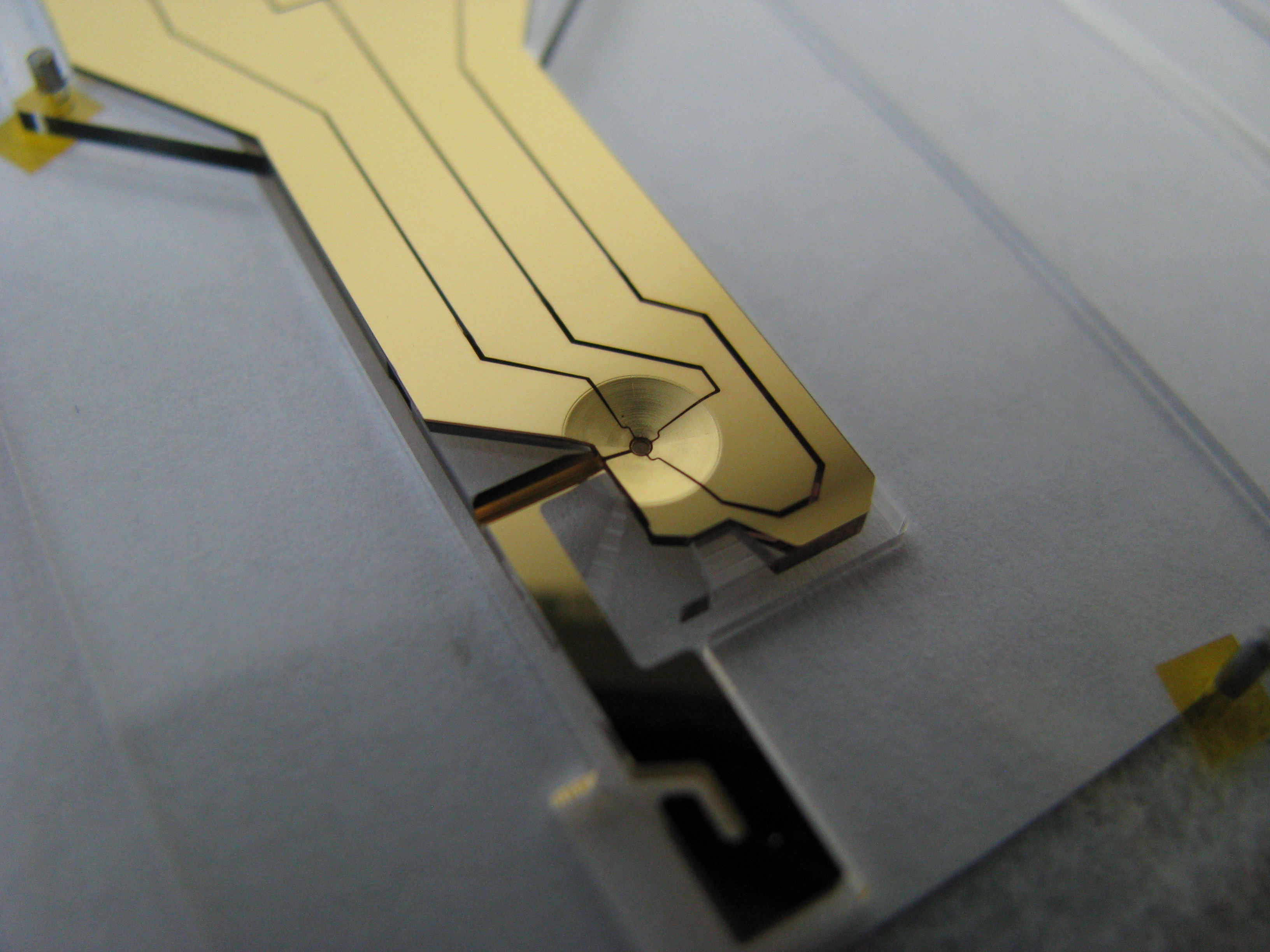
The oblate Paul trap shown after coating. The ion loading port is at 5 o’clock and the RF access port at 8 o’clock
Fabrication Considerations
Uniquely, the UCLA design incorporates numerous subsurface ports, including one port used in part as a RF feedthrough. Any asymmetry in the trapping field due to a surface lead feeding the RF ring is minimized by burying it in a subsurface channel beneath the surface DC control electrodes. The obvious constraint of having this port be electrically conductive throughout posed a unique fabrication challenge.
Eight in-plane ports are seen leading to the center trap bore. The seven through-ports with openings on the platform edge are used for free space optical access. Two of them have dual roles: The one leading directly off to the left will support the RF lead electrode to the center ring, and the asymmetrical tapered hole leading off the bottom platform edge is also used to load the trap with the neutral atoms for ionization.
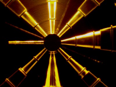
The UCLA oblate Paul trap:Eight subsurface ports are machined inside the trap platform substrate (shown here before electrode coating). The RF access port is at 6 o’clock, and the ion loading port at 3 o’clock.
The trap shown installed in a UHV chamber. Note the metallized ribbon that is used to connect the RF source to the RF electrode. This RF feed is located away from the various DC electrode feeds. This arrangement minimizes any parasitic capacitance between the RF and DC/Ground electrodes (Capacitance control is an important part of custom trap design).
