The trap described here was fabricated at Translume under the direction of Dr. Mark Dugan, in collaboration with Dr. Georg Bollen and Dr. Ryan Ringle (both from the Facility for Rare Isotope Beams, Michigan State University).
Design Overview
The Penning trap uses a combination of static electric and magnetic fields to achieve 3-D confinement of charged particles. Radial confinement is provided by the magnetic field; while the axial confinement is provided by an electrostatic potential. Ideally this potential is quadrupolar.
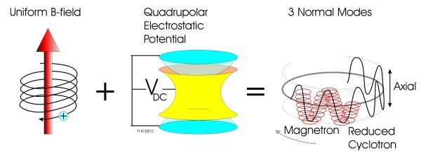
Simplified Penning Trap
Although traps utilizing an hyperboloidal electrode configuration are capable of generating a close approximation to a quadrupolar potential over a large volume, their accurate manufacturing is difficult. Consequently, one often uses traps that are easier to fabricate, even if they have shapes that deviate considerably from the ideal hyperbolic geometry. Cylindrical Penning traps, for example, are common.
In its most basic form, the cylindrical ion trap (CIT) is formed of a central cylindrical ring electrode, and is terminated by two end cap electrodes. This geometry is obviously a distant approximation of a hyperbolic-shaped trap. As a result, the electrostatic potential, in a basic CIT, has a quadratic shape only at or very near the trap center. However, with the addition of compensation electrodes, which are inserted between the central ring electrode and the end cap electrodes, one can drastically minimize the potential anharmonicities, without affecting the trap other parameters, such as trap depth.

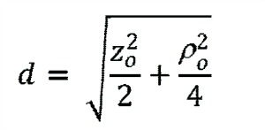
For such a configuration, the on-axis cylindrically symmetric potential can be expanded as:
![]()
Where parameter d is a function of the trap diameter (r) and the axial separation (z0) between the trap center and the endcap edge
Deviation from a pure quadratic is expressed by higher-order (n>2) Cn terms. These anharmonic terms are a source of frequency shift. Optimizing the location and width of the compensation electrodes, the higher-order terms can be minimized.
Design Implementation
In order to take full advantage of the performance enhancement brought by the addition of compensation electrodes, the various elements forming the trap need to be precisely positioned with respect to each other.
To address this critical requirement, the Penning microtrap fabricated by Translume has a core section that is machined from a single piece of fused silica glass. This glass monolith includes (from top to bottom) a first end cap, a compensation ring, a central ring, a second compensation ring, and finally a second end cap. The rings are machined to form isolated electrodes after metallization.
The central ring forms a single electrode, and the same applies to each of the end caps. Each of the compensating ring is divided in four electrodes (used to control and track the motion of the trapped ions). Thus the fused silica glass monolith forming the core of the microtrap contains a total of 11 electrodes (1 central ring electrode, 8 quad electrodes, and 2 end-cap electrodes).
 Looking down the central bore hole of a prototype. (Right) Model showing some of the electrodes and the associated electrical access tunnels")
Fabrication Considerations
Connecting the internal electrodes - central ring and two sets of quad-electrodes - located deep inside the central bore required pursuing the fabrication of novel subsurface horizontal feedthroughs. These pathways were found to have a low electrical resistance while being reliable and robust.
Follow-up Developments
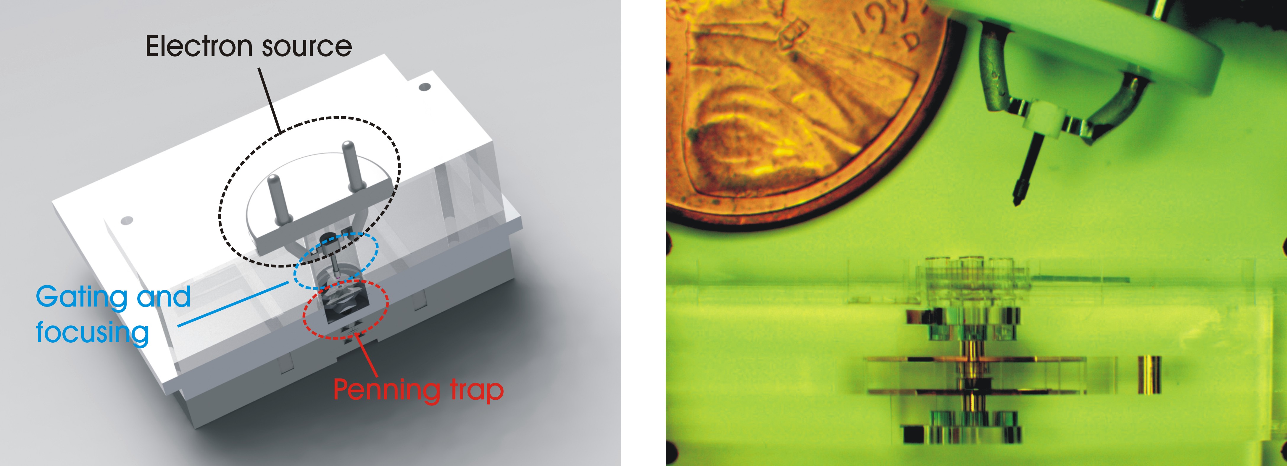
Subsequently a section including an LaB6 electron source with focusing and gating electrical valves was added to the Penning trap core. As shown in the photo below the smallest commercial LaB6 electron source is much larger than our Penning Trap.
End caps extensions and a Faraday plate where also added.