
Dr. Philippe Bado
The trap described here was fabricated at Translume under the direction of Dr. Mark Dugan. The initial design was provided by Dr. Helene Hainzer and her co-workers at the University of Innsbruck. Some features were modified byTranslume.
Reference: “Controlling Two-Dimensional Coulomb Crystals of More Than 100 Ions in a Monolithic Radio-Frequency Trap”, Dominik Kiesenhofer, Helene Hainzer, Artem Zhdanov, Philip C. Holz, Matthias Bock, Tuomas Ollikainen, and Christian F. Roos
PRX Quantum 4, 020317 – Published 28 April 2023
Application
The design of this trap was optimized by the end-users for quantum simulation involving a large number of individually controllable particles. Control over large ion crystals is challenging: Keeping a long one-dimensional crystal linear requires extremely anisotropic trapping potentials, ultimately limiting the number of ions that can be controlled with high fidelity. An alternative pathway to scale up trapped-ion architectures is to use a second spatial dimension, which is an approach recently taken by several groups and also the one taken for the experiment described in the referenced article.
")
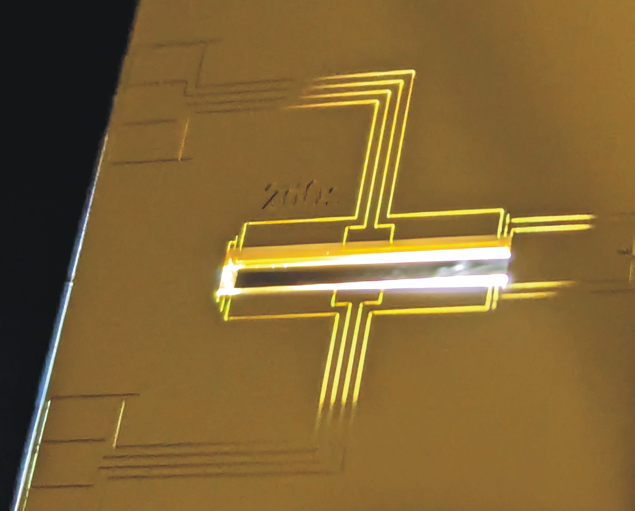
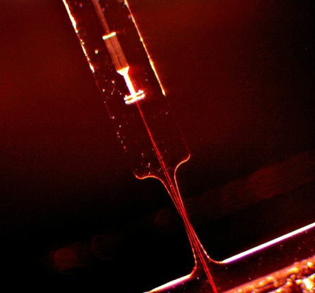
A stationary 91-ion crystal (image courtesy of Dr. Helene Hainzer)
Design Overview
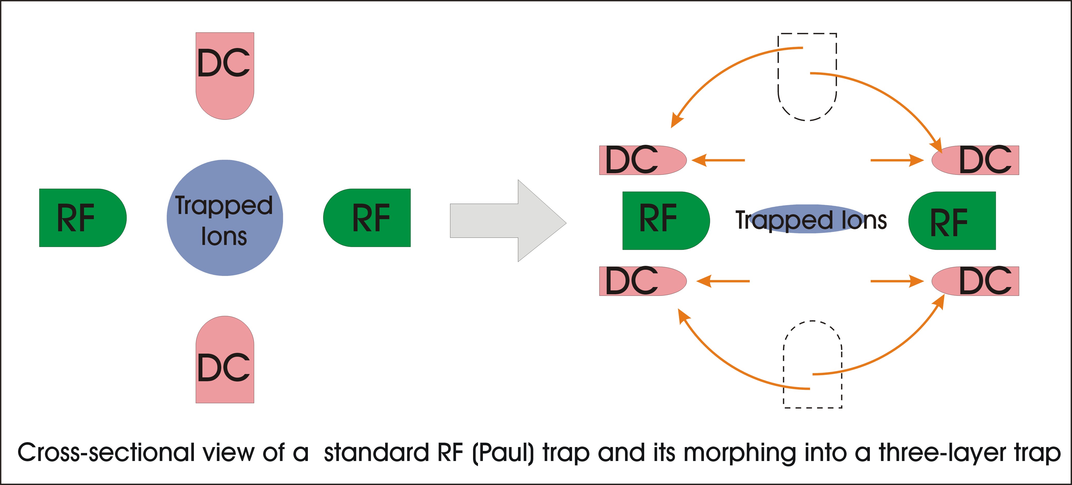
The design differs from a standard linear Paul trap in that the dc blades are split and projected to the top and bottom of the rf blades as shown below. Thus, effectively, the electrode geometry realizes a three-layer trap. Further the dc electrodes are recessed with respect to the rf electrode to allow additional optical access at 45◦ angles from the top and the bottom.
Design Implementation
The designers refer to their trap as a “three-layer” trap; and obviously this trap could have been machined from three separate layers and later hand-assembled. However, this would have almost certainly resulted in alignment imperfections, which would have prevented working with large 2D ion crystals.
Therefore, the trap was fabricated from a single piece of glass – this monolithic approach allowing precise electrode arrangements without the need for hand assembly.
Fabrication Considerations
The trap was designed to operate at an elevated rf voltage of approximately 1 kV peak to peak. The isolation trenches between the RF electrode and the RF ground had to be scaled accordingly.
Related Publications:
- “Controlling Two-Dimensional Coulomb Crystals of More Than 100 Ions in a Monolithic Radio-Frequency Trap”, Dominik Kiesenhofer, Helene Hainzer, Artem Zhdanov, Philip C. Holz, Matthias Bock, Tuomas Ollikainen, and Christian F. Roos. PRX Quantum 4, 020317 – Published 28 April 2023
- “Correlation Spectroscopy with Multiqubit-Enhanced Phase Estimation”, Helene. Hainzer, D. Kiesenhofer, T. Ollikainen, M. Bock, F. Kranzl, M. K. Joshi,, G. Yoeli, R. Blatt, T. Gefen, and C. F. Roos. Physical Review X, 2024; 14 (1) DOI: 10.1103/PhysRevX.14.011033 – Published 29 February 2024
The trap described here was fabricated at Translume under the direction of Dr. Mark Dugan. The trap was designed by the Campbell group [UCLA] and their collaborators at Georgetown University.
Reference: Yoshimura, B., Stork, M., Dadic, D. et al. “ Creation of two-dimensional Coulomb crystals of ions in oblate Paul traps for quantum simulations”, EPJ Quantum Technol. 2, 2 (2015). https://doi.org/10.1140/epjqt14
Application
The Campbell group is using ultra-cold atoms and molecules to learn about the physical processes that permeate the world. Specifically, they are focusing on the physics of quantum mechanical systems that involve many-body interactions, a field where our ability to theoretically describe and numerically simulate the microscopic features is severely limited. Their approach (shared by others, and known in the field as "quantum simulation") is to use well-controlled samples of atoms and molecules in order to build tiny, physical emulators of the physics that they are investigating. By utilizing these atoms as microscopic computers, the Campbell group hopes to be able to pick up where supercomputer simulations become intractable, and to use their quantum simulators to help design and understand new materials, perform demanding computations, and learn about the physical universe.
")
4 rings of ions trapped in an oblate Paul trap (Source: Campbell group - UCLA)
Design Overview
The design (see reference) is optimized to generate an oblate ellipsoidal like effective potential favoring the trapping of ions in a two-dimensional crystal with triangular lattice symmetry. Such a potential can be generated in a Paul trap of azimuthal symmetry with dominant axial confinement. According to the designer, the micromotion in this case is purely radial due to symmetry, and lasers that propagate perpendicular to the crystal plane will therefore not be sensitive to Doppler shifts from micromotion.
Design Implementation
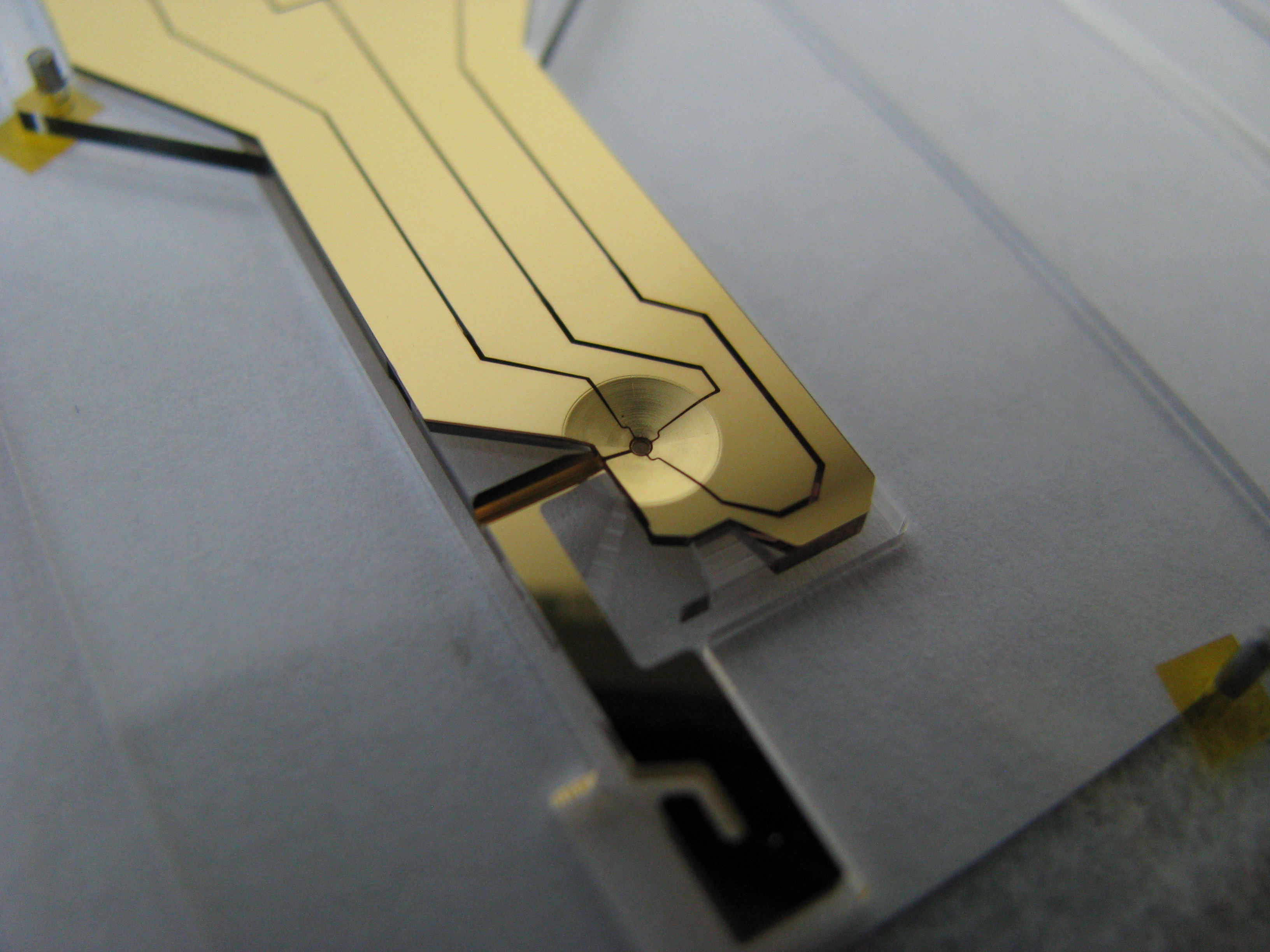
The trap proper is composed of the 5mm outer diameter disc which tapers down to a through hole of 0.5mm diameter and 0.14mm long side wall. These surfaces support the electrodes with the DC control endcaps residing on the upper and lower disc faces and the RF electrode occupying the surface regions constituting the wall and rim of the center hole. The outer frame is such that the DC control electrodes are interfaced through a card connector type clip on the wider end, while the RF is source through the key like structure on the opposite end. This latter RF lead is routed through to the center ring via a subsurface pathway (RF tunnel lead) or as a narrow path on one of the disc faces (surface RF lead). The overall frame size is designed to fit into the UCLA test jig.
The oblate Paul trap has a combination of DC and RF electrodes used to trap ions.
The oblate Paul trap shown after coating. The ion loading port is at 5 o’clock and the RF access port at 8 o’clock
Fabrication Considerations
Uniquely, the UCLA design incorporates numerous subsurface ports, including one port used in part as a RF feedthrough. Any asymmetry in the trapping field due to a surface lead feeding the RF ring is minimized by burying it in a subsurface channel beneath the surface DC control electrodes. The obvious constraint of having this port be electrically conductive throughout posed a unique fabrication challenge.
Eight in-plane ports are seen leading to the center trap bore. The seven through-ports with openings on the platform edge are used for free space optical access. Two of them have dual roles: The one leading directly off to the left will support the RF lead electrode to the center ring, and the asymmetrical tapered hole leading off the bottom platform edge is also used to load the trap with the neutral atoms for ionization.
The UCLA oblate Paul trap:Eight subsurface ports are machined inside the trap platform substrate (shown here before electrode coating). The RF access port is at 6 o’clock, and the ion loading port at 3 o’clock.
The trap shown installed in a UHV chamber. Note the metallized ribbon that is used to connect the RF source to the RF electrode. This RF feed is located away from the various DC electrode feeds. This arrangement minimizes any parasitic capacitance between the RF and DC/Ground electrodes (Capacitance control is an important part of custom trap design).

The trap described here was fabricated at Translume under the direction of Dr. Mark Dugan, in collaboration with Dr. Georg Bollen and Dr. Ryan Ringle (both from the Facility for Rare Isotope Beams, Michigan State University).
Design Overview
The Penning trap uses a combination of static electric and magnetic fields to achieve 3-D confinement of charged particles. Radial confinement is provided by the magnetic field; while the axial confinement is provided by an electrostatic potential. Ideally this potential is quadrupolar.
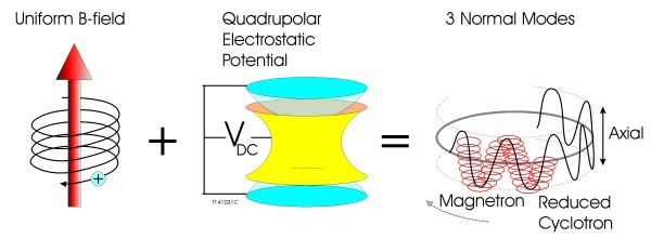
Simplified Penning Trap
Although traps utilizing an hyperboloidal electrode configuration are capable of generating a close approximation to a quadrupolar potential over a large volume, their accurate manufacturing is difficult. Consequently, one often uses traps that are easier to fabricate, even if they have shapes that deviate considerably from the ideal hyperbolic geometry. Cylindrical Penning traps, for example, are common.
In its most basic form, the cylindrical ion trap (CIT) is formed of a central cylindrical ring electrode, and is terminated by two end cap electrodes. This geometry is obviously a distant approximation of a hyperbolic-shaped trap. As a result, the electrostatic potential, in a basic CIT, has a quadratic shape only at or very near the trap center. However, with the addition of compensation electrodes, which are inserted between the central ring electrode and the end cap electrodes, one can drastically minimize the potential anharmonicities, without affecting the trap other parameters, such as trap depth.

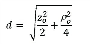
For such a configuration, the on-axis cylindrically symmetric potential can be expanded as:
![]()
Where parameter d is a function of the trap diameter (r) and the axial separation (z0) between the trap center and the endcap edge
Deviation from a pure quadratic is expressed by higher-order (n>2) Cn terms. These anharmonic terms are a source of frequency shift. Optimizing the location and width of the compensation electrodes, the higher-order terms can be minimized.
Design Implementation
In order to take full advantage of the performance enhancement brought by the addition of compensation electrodes, the various elements forming the trap need to be precisely positioned with respect to each other.
To address this critical requirement, the Penning microtrap fabricated by Translume has a core section that is machined from a single piece of fused silica glass. This glass monolith includes (from top to bottom) a first end cap, a compensation ring, a central ring, a second compensation ring, and finally a second end cap. The rings are machined to form isolated electrodes after metallization.
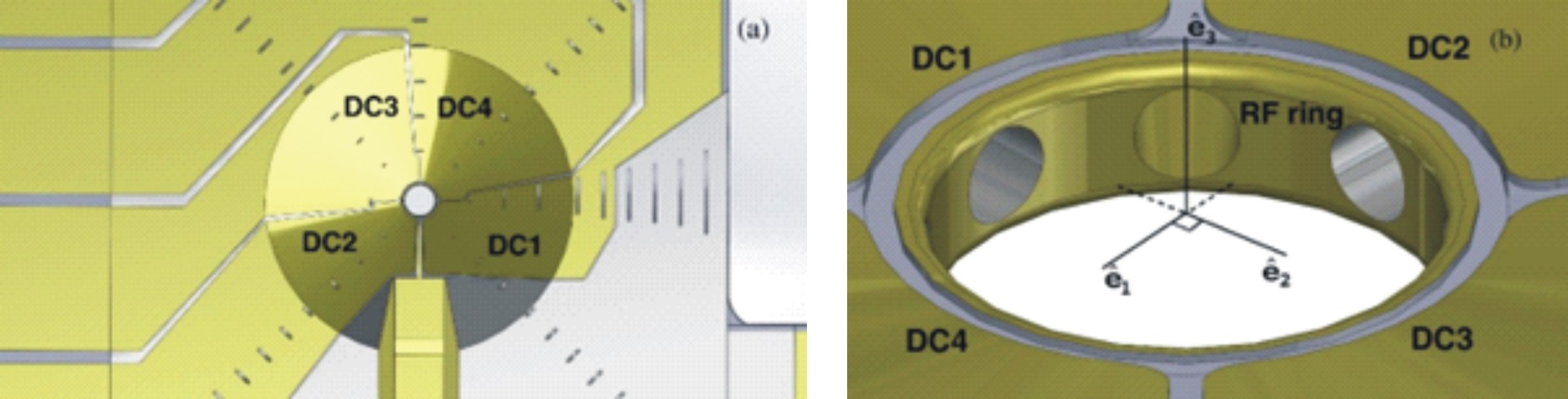
The central ring forms a single electrode, and the same applies to each of the end caps. Each of the compensating ring is divided in four electrodes (used to control and track the motion of the trapped ions). Thus the fused silica glass monolith forming the core of the microtrap contains a total of 11 electrodes (1 central ring electrode, 8 quad electrodes, and 2 end-cap electrodes).
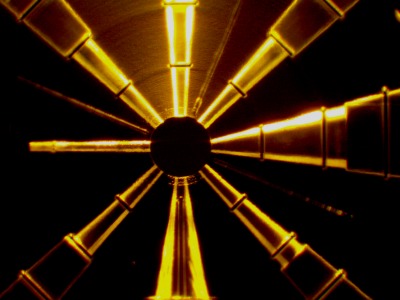
 Looking down the central bore hole of a prototype. (Right) Model showing some of the electrodes and the associated electrical access tunnels")
Fabrication Considerations
Connecting the internal electrodes - central ring and two sets of quad-electrodes - located deep inside the central bore required pursuing the fabrication of novel subsurface horizontal feedthroughs. These pathways were found to have a low electrical resistance while being reliable and robust.
Follow-up Developments
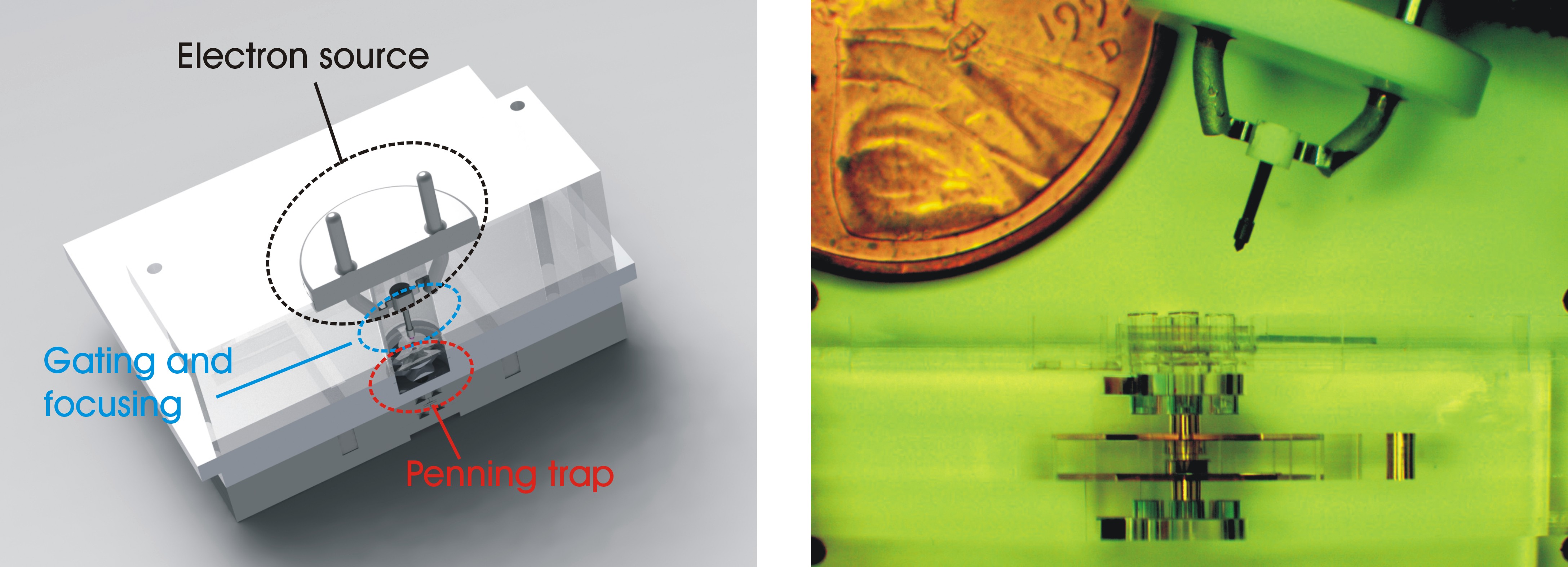
Subsequently a section including an LaB6 electron source with focusing and gating electrical valves was added to the Penning trap core. As shown in the photo below the smallest commercial LaB6 electron source is much larger than our Penning Trap.
End caps extensions and a Faraday plate where also added.
Flexure with Integrated Mach-Zehnder Interferometer
Many customers have discovered that our fused silica flexures, with their near-zero coefficient of thermal expansion, and their almost perfect elastic behavior, provide some exceptional advantages for many demanding metrology applications. Less known is the fact that, if desired, these flexures can be fabricated with integrated optical waveguides. We are reporting here on the fabrication of fused silica notch flexures with integrated Mach-Zehnder waveguided interferometers.
Milliliter, Microliters, Pa, psi and other units commonly used in microfluidic
Fluid volumes used in microfluidics are generally quite small. The most commonly used volumetric units are “milliliters” and “microliters”.
There are a few sure-fire ways to increase the fabrication costs (NRE and per-piece charges) of your custom-made chip.
Nobody likes to pay NRE fees. If you purchase a standard fused silica glass chip or flow cell from our standard product section, you will pay a fixedprice for a single piece (plus shipping). However, if you require a custom glass chip, our quotation will reflect two charges:
The behavior of fluids at the microscale level can differ significantly from the everyday behavior of fluids that we are accustomed to. Factors, such as surface tension and viscosity, start to dominate the physics of microfluidic channels, while gravity plays a negligible role.
Optics-Based Force and Position Micro-Sensors with Fused Silica Flexures
Most micro-mechanical sensors measure an electrical variable (such as capacitance) to measure force or position. Optically-based force and position micro-sensors are far less common, as their fabrication is more complex.